From Compromised To Optimized
Part two of a strategy to minimize TCO.
By: Akhil Docca, Maira Bana, and James Baross
Our previous article, “5 Reasons For Lost Data Center Dollars,” established the main causes of low-capacity utilization, increased downtime and cooling inefficiencies, and examined the impact they have on your costs. We concluded that the best solution is an integrated and continuous modeling process to resolve current problems and model future changes. At Future Facilities, we achieve this using our 6SigmaDCX engineering simulation tool.
Data center performance losses occur almost from day one, but may only manifest themselves much later in the life cycle: a result of creeping changes made over a long period. To counter this, monitoring and continuous modeling are needed — even when you believe that your facility is well operated and not showing obvious issues.
Here we’ll illustrate, through our work with a global banking giant, how the engineering simulation tool has been used to meet owner/operators’ goals. We approached this in three phases: assess, improve, and maintain.
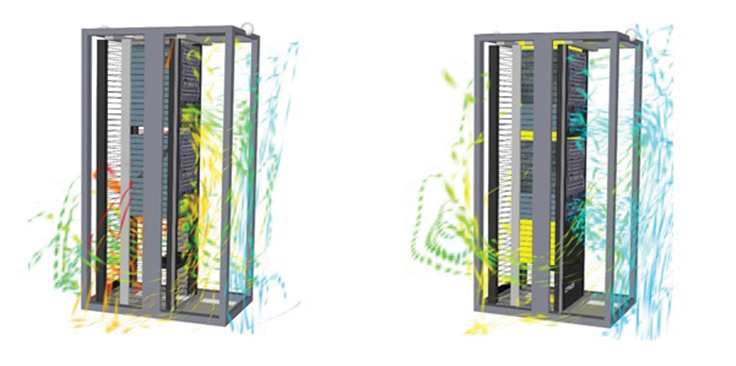
FIGURE 1. Simulation results showed hot air (red and orange streamlines) recirculating within the cabinets. This was overheating the IT and threatening availability. (Right) We used the virtual facility to test custom blanking (the yellow panels) within the cabinet. Notice how the blanking resolves the recirculation issues.
STAGE 1: ASSESS
In this case study, engineering simulation was used to analyze and optimize a three-year-old, Tier IV, mission critical data center. The facilities team asked for our help in reducing PUE, but the IT teams wanted guarantees that raising air temperature wouldn’t jeopardize any equipment or erode the data center’s capacity.
We performed a detailed on-site survey, which allowed us to create a 3-D model of the data center (called the virtual facility). Our automated integration tool then pulled in live monitoring and IT asset data from the customer’s DCIM stack.
Equipped with this live data, we then verified the accuracy of the virtual facility — ensuring the simulation was capturing the full physics of the airflow and temperature.
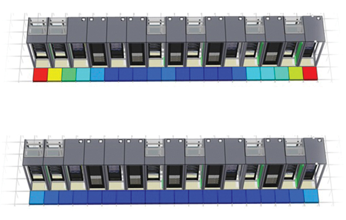
FIGURE 2. The red, yellow, and green tiles at the ends of the top row denote low airflow to the equipment in the cabinets. That threatens uptime. In the bottom row, the floor grilles have been replaced, resulting in better flow.
STAGE 2: IMPROVE
The virtual facility was used to identify three key shortcomings of the data center, and to establish where improvements could be made. This allowed the client to map out the consequences of IT or facility changes without making expensive changes in the actual facility.
- Internal rack recirculation. Simulation of the existing data center design revealed that hot air was recirculating inside cabinets (Figure 1). This was causing servers to overheat — increasing risk to the business. Using the engineering simulation tool to visualize the problem, we designed and simulated customized blanking and then installed this in the facility. The custom blanking reduced the IT inlet temperature by nearly 25%.
- Airflow delivery. The simulation results also revealed that the floor grilles at row ends were supplying less airflow than grilles closer to the center (Figure 2), resulting in higher inlet temperatures for nearby cabinets.
To address this, we simulated models with different grille types at these locations. This allowed us to determine which of the grilles offered the most improvement without needing physical testing.
- Energy costs. We then identified that significant energy savings could be achieved by raising air temperatures in the room (Figure 3). We simulated gradual increases in supply air temperature and found that it could safely be increased from 16°C to 22°C (60.8°F to 71.6°F) without risking availability.
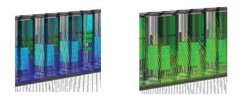
FIGURE 3. This row is being over cooled, which equates to wasted energy and overspend on cooling. (Right) The supply air temperature has been increased to the optimum level — it is warmer, but still safely within the standards recommended by ASHRAE.
RESULTS
Together, the improvements in airflow delivery and rack recirculation reclaimed 10% (350 kW) of lost capacity. This translated to $8.75m, based on the client’s investment. The increase in cooling airflow temperatures resulted in a further saving of $1.15m and a 15% PUE reduction. Importantly, this was achieved at no cost to availability. In total, $10 million was saved.
STAGE 3: MAINTAIN
To ensure that the virtual facility model is always up to date, we integrated with the customer’s DCIM solution to allow direct import of current inventory and future deployments. In addition, we brought in live power and temperature data from the racks. This helped to reduce errors associated with data entry and allowed the customer to detect potential deviations from their best-case scenario and decide how to deal with them.
CONCLUSIONS
Even in the most well-managed facilities, the day-to-day realities of operations don’t match the original facility design. These differences add up and mean that you’re often not getting the capacity you paid for. Engineering simulation can help you spot performance issues — both current and future — and model potential solutions to determine the best outcome. Using this approach, we helped a global banking giant achieve $10 million in savings.
Read the full article in Mission Critical Magazine.
Part One of the series can be found Here.
